Transporter Magazine Volkswagen Vans Volkswagen Vans Tin Tops High Tops Westfalia and More
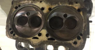
Fresh AMC heads on a late Vanagon can transform the way a boxer pulls. But if your first start yields a lumpy idle, a rich exhaust, or worse—a 2400‑RPM scream—you’re likely fighting two post‑rebuild realities: hydraulic lifters that haven’t fully pumped up and pushrods that may have momentarily mis-seated on the lip of their lifter cups. The cure is not guesswork. It’s methodical: reseat every pushrod, set 1.5 turns of hydraulic preload (no more), and then walk through a precise Digifant idle verification.
This guide documents a real 1989 Vanagon 2.1 MV (automatic) repair from first-start to final idle, with step‑by‑step procedures you can trust in the driveway or the workshop.
The Real-World Story (What Happened and Why It Matters)
The van ran fine before the head job. After installing new AMC heads, the first run was rough, rich, and inconsistent. Two pushrods—one on each bank—had bounced onto the lip of their hydraulic lifter cups because the lifters weren’t pumped and the adjusters were left loose. That put the affected valves slightly open, tanking idle quality and driving the ECU rich.
The fix was straightforward but exacting:
- Loosen the rocker shaft evenly.
- Reseat each pushrod so it sits fully in the lifter cup.
- Tighten the shaft while confirming each rod stays centered.
- Set 1.5 turns of preload on every valve—no “extra” initial turns.
- Warm, drive a couple of break‑in cycles, change the oil to purge any coolant left from the blown head gasket event, and re‑check preload at 1.5 turns.
The engine immediately ran smoother. A subsequent high idle was resolved by standard Digifant checks (covered below). The takeaway: correct pushrod seating and 1.5‑turn preload are foundational; everything else is diagnostics, not band‑aids.
Why Hydraulic Lifters Can Bite After a Head Job
Hydraulic lifters bleed down while a van sits or during engine work. On restart, a soft lifter allows extra lash. If the rockers are adjusted loose to help initial fire‑up, the pushrod can briefly ride the rim rather than the lifter’s cup. That lever effect holds a valve slightly open—instant misfire, low vacuum, and rich running. Once the lifters pump and you set proper 1.5‑turn preload, the system self‑stabilizes.
Publisher’s Note: We deliberately avoid the old habit of an “initial 2‑turn” setting. On the MV, go straight to 1.5 turns from true zero lash, then re‑verify after your early break‑in runs and oil changes. This aligns preload with the lifter’s working range and avoids over‑preload when parts heat‑cycle.
Hydraulic Lifter Preload on the Vanagon MV: Deep Dive
- What preload actually does: It positions the internal plunger in the lifter’s travel window so oil pressure can maintain zero lash as parts expand.
- Too much preload: Can hold valves off their seats hot, kill idle vacuum, and overheat exhaust valves.
- Too little preload: Lets lash reappear, makes noise, and risks pushrod hop and adjuster/valve tip hammering.
- Target on the MV: 1.5 turns from true zero lash is the sweet spot for stock cams, stock pushrods, and AMC heads.
- Confirming zero lash: Use fingertip feel only—when vertical play just disappears, stop; that’s your baseline.
Break‑In & Oil Strategy after Coolant Contamination
- Short initial drives: 10–20 minute heat cycles to fully warm the oil and lifters.
- Early oil & filter changes: Coolant from a prior head‑gasket failure can linger. Change oil and filter after the first heat cycles and again after ~200–300 miles.
- Post‑change preload check: Re‑verify 1.5 turns across all eight valves once the engine has stabilized.
Step‑by‑Step: Reseat Pushrods & Set 1.5‑Turn Preload Like a Pro
Tools: 13 mm socket/wrench, torque wrench, good light, small mirror, paint pen, throttle body cleaner, rags.
Cylinder #1 at TDC (Compression)
Align the flywheel TDC mark and confirm the distributor rotor points to #1. Both #1 rockers should be on the base circle.
Loosen the Rocker Shaft Evenly
Crack each nut ½–1 turn, alternating, to relieve spring load without stressing the stands.
Reseat the Pushrods
Spin each pushrod with two fingers. If it’s perched on the rim, you’ll feel a tiny drop/click as it centers into the lifter cup. Use a mirror and light for visual confirmation through the tube if needed.
Re‑tighten and Torque
Snug the shaft evenly and torque to ~25 N·m (18 ft‑lb). Ensure stands sit fully on their bosses—no trapped washers or cocked shims.
Find True Zero Lash
Back the adjuster until you can feel up‑down play at the rocker. Turn in gently until the play disappears—no spring compression yet. That’s zero.
Set Preload to 1.5 Turns
From zero lash, turn the adjuster 1.5 turns in. Lock it down.
Work a Smart Rotation Order
A field‑proven method is to rotate the engine backwards in half‑turn increments to keep geometry friendly while you work:
- Start #1 (confirm marks).
- Rotate backwards to #2 and set both.
- Refit that cover if you like, rotate another ½ turn backwards and do #3,
- Then another ½ turn to do #4. This approach minimizes pushrod hop‑out as you rotate.
Warm, Drive, Re‑Check
Bring the engine to temperature. Make a couple of short break‑in drives. Because a blown head gasket can push coolant into the oil, change oil and filter early, then re‑verify 1.5‑turn preload across all eight valves.
Geometry & Sanity Checks (When It Still Won’t Behave)
- Rocker Tip on Valve Centerline: At about half‑lift, the contact patch should be centered. Wild off‑center patterns suggest geometry or stem height issues.
- Correct Pushrods: Don’t mix 1.9 and 2.1 parts. Aftermarket chromoly sets can vary—verify length if preload range is odd.
- Hydraulic vs Solid Lifters: Make sure parts match your pushrods and adjustment method.
- Bent Pushrods: Any event that held a valve open can tweak a rod. Roll on glass to check.
High Idle After the Mechanical Fix? Use This Two‑Minute Decision Tree
Once compression and vacuum are restored, any extra air path shows up as high idle. Diagnose before you touch the throttle stop.
Pinch the ICV Hose (ICV → Plenum)
- RPM drops hard or stalls: Excess air is through the idle valve path. Check for valve modulation.
- Little/no change: Air is bypassing the ICV—vacuum leak or throttle held open.
Does the ICV Buzz with Key On/Idle?
- A healthy system buzzes continuously. If yours just thumps at key‑on/off but doesn’t buzz, the Idle Control Unit (ICU) isn’t modulating or the valve is sticky.
Quick Electrical Checks:
- ICV coil: ~7–10 Ω across pins (unplugged).
- Harness feed: ~12 V on one pin with key on.
- ICU pulsed ground: a test light from battery + to the other pin should flicker at idle. No flicker = no modulation (TPS idle not seen, no RPM signal from coil –, poor grounds, or failed ICU).
Throttle Really Closed?
- Lever must rest on the stop with a positive feel.
- Ensure a touch of cable slack (including cruise if fitted).
- Clean carbon from the plate and bore.
Usual Vacuum Leaks Right After Head Work
- Brake booster line & check valve: Clamp to test.
- Crankcase breather tower & hoses: Cap the plenum port as a test; inspect tower O‑ring and diaphragm.
- S‑boot (AFM → TB): Hairline cracks in the ribs; mis‑seated clamps; uncapped nipples.
- Injector seals & TB gasket: Spray/propane test for rpm changes.
- Plenum‑to‑runner short boots & runner‑to‑head gaskets: Boots 90% seated = 2000‑rpm idle.
Digifant Idle Stabilizer Bypass Procedure (MV)
- Warm the engine fully (cooling fan cycles).
- Locate the idle stabilization bypass connector near the left firewall (two‑wire plug loop on many MVs).
- Unplug/bypass per your service manual so the ICU/ICV are out of the circuit.
- Set idle with the throttle‑body bypass screw to ~850–900 rpm (auto in P/N).
- Set ignition timing to spec while still bypassed.
- Reconnect stabilization and confirm ~850–900 in Park, ~700–800 in Drive.
TPS Adjustment & Continuity Sanity Check
- With throttle on the stop, the idle contacts must have continuity. The switch should open just off idle and the WOT contact should close at full throttle.
- If the ECU never sees idle, the ICU won’t modulate the valve; verify switch function and harness continuity.
Torque & Specs Quick Sheet
- Rocker shaft nuts: ~25 N·m (18 ft‑lb)
- Hydraulic lifter preload: 1.5 turns in from true zero lash
- Target hot idle (auto): 850–900 RPM (P/N), 700–800 (D, foot on brake)
Tools & Consumables Checklist
- 13 mm socket/wrench, torque wrench
- Inspection mirror & pen light
- Hose pinch clamps
- Carb/throttle cleaner & lint‑free rags
- Injector O‑rings and TB gasket (if suspect)
- Dielectric grease for connectors; Scotch‑Brite for grounds
- LED test light + multimeter for PWM checks
Affiliate Picks (Editor’s Bench)
Contextual, honest recommendations help readers finish the job right.
- Editor’s Pick: Viton pushrod tube seal kit — better heat‑cycle resilience.
- Budget Fixer: Hose pinch clamp 2‑pack — instant ICV/booster isolation.
- Workshop Essential: LED test light + DMM — verify ICU PWM in seconds.
- Nice to Have: Compact mirror + light — confirm lifter cup seating visually.
Image Plan & Alt Text (SEO‑Ready)
- Pushrod correctly seated in hydraulic lifter cup — “Vanagon 2.1 MV pushrod seated in lifter cup, correct orientation”
- Even rocker‑shaft torque — “Torquing Vanagon rocker shaft to 18 ft‑lb to lock in preload”
- Zero‑lash close‑up — “Finding zero lash before 1.5‑turn hydraulic preload on MV”
- ICV hose pinch test — “Pinching idle control valve hose to isolate high idle air path”
- Throttle lever on stop — “Throttle plate fully closed with proper cable slack on Vanagon MV”
- S‑boot inspection — “Checking AFM‑to‑throttle S‑boot ribs for splits after head work”
FAQs
Is 1.5 turns enough on brand‑new or bled‑down lifters?
Yes. Set 1.5 turns from true zero lash, then re‑check after early break‑in runs and oil changes. This keeps preload centered as lifters normalize.
My ICV thumps but doesn’t buzz—what now?
Verify 12 V feed, 7–10 Ω coil, and pulsed ground from the ICU with a test light. If the hose pinch drops idle but there’s no flicker, chase ICU power/grounds, TPS idle signal, and the coil‑negative RPM lead.
Do I have to rotate the engine backwards for your sequence?
No, but the backwards half‑turn method keeps the pushrods happy while you work, reducing hop‑out risk.
After AMC heads, do I need shorter pushrods or shims?
Only if you cannot reach zero lash with the adjuster or need excessive preload. Minimal pedestal shims are fine to diagnose; long term, order correct‑length pushrods if geometry demands it.
Idle still high after all this?
Confirm throttle on stop, no vacuum leaks, and ICV modulation. Only then touch base idle and timing with stabilization bypassed.
What are early warning signs of a coolant‑in‑oil issue after a blown gasket?
Milky residue on the oil cap or dipstick, rising oil level, and sweet smell. Prioritize short heat cycles and immediate oil/filter changes.
Can a reman Ford AFM cause high idle?
It can if any bypass port or nipple is left uncapped or the S‑boot doesn’t seal squarely. Double‑check the adapter, clocking, and clamps.